All of a sudden, robots are everywhere. I even have a newsletter all about them! It may seem like this is because of advancements in artificial intelligence—and in large part, it is. But it is also because of rapidly advancing capabilities in the physical machines themselves, advances that are driven by improvements in actuator technology.
Actuators make robots move. They are, in brief: motors, reducers, sensors, bearings, electronics, brakes and housing.
An actuator’s fundamental role is to take a motor spinning fast and weak and use that to power a joint that must move slow and strong. To date, robots have been jerky, sudden and awkward—and expensive—McKinsey estimates actuators take up 40–60% of a humanoid machine’s bill of materials (BOM).
Improvements in actuators will pave the way for better and cheaper robots. It’s well worth understanding the technology that will fundamentally reshape our world.
This document is divided into three parts.
Part I is economics: what an actuator costs, what levers exist to lower those costs and why “build vs. buy” is barely a debate at the frontier. I’ll address the uncomfortable reality that for the foreseeable future, advancing in robotics requires maintaining good trading terms with China.
Part II is anatomy: what an actuator is made of and how the pieces work together. You’ll understand how a wide range of factors—from patent law to heat management to avoiding stray magnetic fields—influence design choices. If you can understand an actuator’s strengths and weaknesses, you can more easily interpret new breakthroughs and separate substance from hype.
Part III is the factory: this section brings it all together, where we go step-by-step from raw stock to finished unit and make your very own actuator (provided you already have a factory—you do have a factory, right?).
This is, as far as I have found, the most comprehensive overview of actuators. See you in 15,000 words.
Why is the humble actuator the component every robotics executive counts electric sheep over?1BEEP!1Is the implication that robotics executives are, themselves, robots? Possibly.
To reiterate: they’re expensive. In addition to the McKinsey report above, Interact Analysis pegs joint actuators north of 30% of BOM (over 50% in simpler robots); and Bank of America's teardown of a ~$35,000 China-built humanoid treats the actuator system as a clear majority of cost.
But also they genuinely are the differentiator between a robot that moves well and can do useful things versus one that doesn’t.
A car has one drivetrain; a humanoid has a drivetrain at every joint (it has a lot of joints). Optimus carries ~28 before you count fingers. High-torque leg actuators run $1,000–5,000 apiece across the leg; a single roller screw inside the priciest of those costs $1,350–2,700 on its own. Morgan Stanley pegs Optimus Gen 2’s build cost around $55,000—legs alone near $21,000—against Tesla’s stated consumer target of $20,000. The current math does not work. It requires actuator costs to fall a lot; here’s how they might.
One note before jumping in: if terms like QDD, harmonic drive or roller screw don't mean anything to you yet, don't worry about it other than to know that they’re different types of actuators. They’ll be addressed in Part II, but hover over jargon for its glossary definition. This section is more about how companies are distinguishing themselves from each other via their actuation choices.
This is a snapshot of who uses which actuators today. Contents may have shifted during flight, and one company I dismiss with a glib joke will presumably become a $1T juggernaut, at which point this section becomes a humiliating “remember when” for me. Remember too that some of these companies may be, let’s say, overstating: much of the game right now is fundraising. VCs can be a friendlier audience than consumers, but in the end, it’ll all shake out. As Benjamin Graham said: in the short run the market is a voting machine; in the long run, a weighing machine.
Many more Chinese companies. Treating “Chinese humanoids” as one entry is like treating “American tech companies” as one—but there are commonalities: China ships ~90% of the world’s humanoid units with an estimated $20B in government support, atop the planet’s densest supply chain.
AgiBot: 2025’s actual shipment champion at 5,168 units, among the first to 10,000 cumulative—5,000 to 10,000 in three months. XPeng’s IRON6BEEP!6Kidding! Remember when everything was cake? I blame COVID. Anyway—it was actually a robot, of course.: 82 DOF, harmonic-jointed hands, solid-state batteries and it walked so smoothly a crowd accused it of being a person in a suit, whereupon XPeng cut one open on stage, revealing it was not a human, or a robot, but in fact cake. UBTech’s Walker S2 has 800M+ yuan in orders and mass production underway. Kepler ships the roller-screw “hybrid” K2; Fourier pivoted from rehab exos to the touch-sensitive GR-3 care-bot;7BEEP!7GR-3 carries 31 pressure sensors and dual hot-swappable batteries. The swappable part matters more than it sounds, since a care robot that sits down to recharge for two hours has, functionally, abandoned the person it was caring for. Xiaomi previously claimed 90% task success in car-assembly pilots; EngineAI and Booster do athletics (~43 actuators a machine); Noetix’s Bumi sells for about $1,400.
Morgan Stanley responded by nearly doubling its Chinese shipment forecast. The pattern there is less variation in actuators, but more actuators—tons of standard QDD modules and harmonic joints.
The supporting cast. Lightning round, let’s go!
NASA’s Valkyrie: all-SEA gentleness when money is no object. Fauna’s Sprout: a child-sized 29-DOF development humanoid on deliberately backdrivable, impact-gentle motors—$50,000, and bought by Amazon within two months of launch. Neura (Germany): 4NE1 claims 100 kg lifts on its joint technology, a Schaeffler partnership for actuators to 250 Nm and a Porsche-designed next gen at CES 2026. Israel’s Mentee: in-house torque-dense actuators that Mobileye paid $900M for. Collaborative Robotics’ Proxie: the anti-humanoid, a wheeled swerve-drive base tugging 1,500-lb carts. London’s Humanoid: the outsourcing bet—Schaeffler supplying half its actuators through 2031, Bosch building the robots. RIVR’s wheels-on-leg-tips delivery quadrupeds: also Amazon-acquired, same month as Fauna—a pattern. Kawasaki’s Kaleido: teleoperated aspiring first responder.8BEEP!8At 99 kg, Kaleido is a big boy. NEO is 30 kg, and most competitors cluster under 70. Its 2025 demos included sweeping floors, and it’s supposedly meant to be deployed in disaster areas, which is kind of the two sides of humanoids in a nutshell: they’re either universally applicable or desperately searching for a clear application. And Disney’s BDX droids, whose Imagineers call their individually characterized little actuators “the secret sauce”—Disney is probably not winning the Droid Wars, but fun to know they’re somehow in it. And, finally, pour one out for Honda’s ASIMO9BEEP!9Thirty-four harmonic-driven servos, honed over decades in Honda’s famously secretive R&D department, canceled a few years before the industry unanimously decided humanoids were the future after all. Tough break for a robot that spent twenty years convincing the public machines could climb stairs.—harmonic-driven servos, development halted in 2018 (public demos ran to 2022) after over a decade of waddling around at demos.
Cost, supply, identity—in ascending order of importance.
The obvious response to “actuators are expensive and you need thirty” is “fine, buy thirty good ones.” You can! You’ll just be a robot assembler with no moat, at great expense—but you can!
A real market exists: Harmonic Drive, Nabtesco, Nidec, Schaeffler, plus a fast-growing Chinese cohort (Leaderdrive, Suzhou Green Harmonic, Ningbo ZD Leader, Zhaowei) and integrated-actuator sellers like RobStride, Unitree and Fourier. The reducer market alone is projected to grow from ~$39M (2024) to ~$580M (2032)—a 40% CAGR; the supply chain is, uh, gearing up.
So why does nearly every serious humanoid company build its own?
First, cost. If actuators are half your robot, paying a vendor’s margin on top is brutal. Second, supply. 26-plus-week lead times on purchased harmonic assemblies are not unheard of. And, third, and most importantly… identity.
As Part II covers at some length, the actuator is where hardware meets control software: the commutation, the force estimation, the thermal behavior. A company optimizing compliant, quiet home robots makes different actuators than one optimizing raw strength. It is what makes your robot yours—cost, supply security and differentiation all living in the same housing, which is exactly the recipe for vertical integration.
Japan’s Yaskawa is a telling case of this point. They started with an actuator business, before deciding to spin up their own humanoid division. If the thesis that the actuator is the true hardware differentiator holds, I would not be surprised to see some of the companies listed above follow the same path.
✶The vertical-integration wave
Companies are bringing actuator production in-house. Tesla makes its own motors and reducers on a decade of automotive muscle. Figure builds in-house. 1X builds in-house. Apptronik designs in-house and contracts the factory work—a hedge that keeps the IP while renting the capital.
What you do not see anywhere serious is an integrator buying its muscles at retail; the companies that skip actuators entirely (Physical Intelligence, Generalist, etc.) are deliberately brains-only.
There’s a regional dimension too: China’s manufacturers—Unitree above all—enjoy cheaper components and faster scaling, competing primarily on cost. A G1 at $13,500 is reportedly built on ~$9,000 of components, a number that presumably haunts American manufacturers. Recall that Tesla, owned by the world’s richest man and piggybacking on car-and-rocket manufacturing, builds Optimus at many multiples of that. America’s bet is autonomy and software on top, cost-parity underneath—and whether that parity arrives is, in large part, an actuator-manufacturing question.
✶What an actuator should cost to build: scale is the whole game
Every cost decision gets multiplied by ~30 joints per robot, times however many robots the world builds—and the forecasts for the buildout are enormous: Goldman Sachs projects 250,000+ humanoid shipments by 2030 and 1.4M/year by 2035; Morgan Stanley goes to a billion humanoids and $5 trillion by 2050.10BEEP!10The intermediate math: MS’s path runs through 13 million humanoids in service by 2035, with unit prices falling from ~$200,000 toward ~$50,000 by mid-century—a curve that assumes everything this essay says about grinding cost off gears happens, at scale, for decades. Take that seriously for a second: a billion robots at thirty actuators each is thirty billion actuators. To do some complex math here, a dollar shaved off one actuator translates to thirty billion dollars. Grinding versus net-forming, billet versus casting, bought bearing versus integrated raceway: each is a rounding error on one unit and a ludicrous fortune across the global fleet.
Manufacturing process is strategy, and the company that gets its actuator cost down to the baseline gets to set the price. The question, then, isn’t “what does an actuator cost?” but “what would it cost you to build one, and which steps reward scale the most?”
Every actuator has a few expensive, difficult-to-access chunks of geopolitics.
Starting with a bit of a downer: the single most important material in the actuator, the one that is in nearly every actuator, comes almost entirely from our chief geopolitical rival, China.
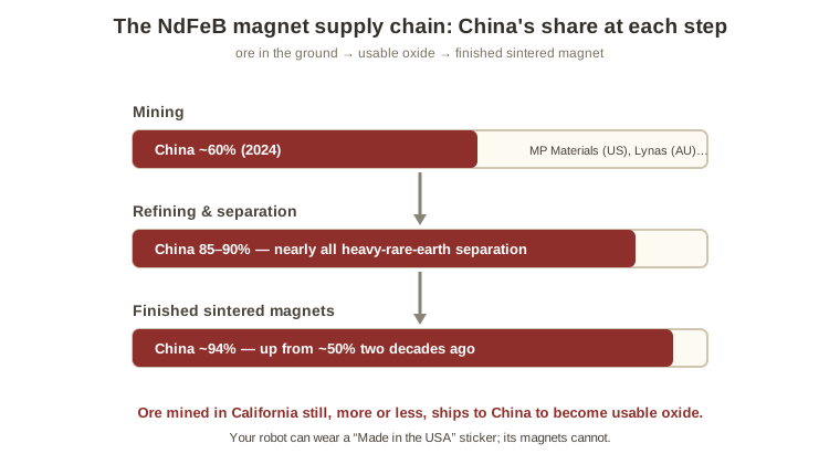
Rare earth NdFeB (neodymium) magnets rest on two pairs of rare earths—neodymium/praseodymium for strength, dysprosium/terbium for thermal stability—and the supply chain runs: mining (China ~60% in 2024; MP Materials in California and Lynas in Australia are non-China players), refining (China 85–90%, and nearly all heavy-rare-earth separation—ore mined in California still, more or less, ships to China to become usable oxide) and finished sintered magnets (China ~94%, up from ~50% two decades ago). Your robot can wear a “Made in the USA” sticker; its magnets cannot.
The supply chain risks are elevated. In April 2025, China imposed export controls on seven rare earths plus finished magnets, with licenses taking months to clear; Musk attributed an Optimus delay directly to the “magnet issue.” A second wave followed in October 2025 before a one-year suspension, to November 2026, as part of a trade truce. The licensing regime is Kafkaesque—theoretically 45 days, often four months—which forces extra inventory (bad) and discloses IP to Beijing (worse). And the only thing worse than depending on China is not depending on China: Morgan Stanley—whose own model calls for a billion humanoids—projects NdPr demand rising 167% above 2030 levels by 2050, with supply falling behind by 26–35% within two decades. “Guys, we ran out of magnets” is a realistic future state.
The alternatives are limited.
Ex-China supply. MP Materials began producing finished magnets in Fort Worth in December 2025—its largest shareholder being, uh, the Pentagon;11BEEP!11From 2027, US defense contractors are barred from buying Chinese-made magnets—which leaves robotics firms technically free to keep sourcing from China, and means (one has to imagine) that early domestic capacity gets spoken for by fighter jets before any humanoid knee sees a magnet. combined ex-China share is still projected under 10% by decade’s end, and defense demand assuredly gets the first claim. Germany’s Vacuumschmelze (e-VAC Magnetics) is building in South Carolina.
Recycling. Noveon’s magnet-to-magnet process, a January 2026 LG partnership, could produce significant supply in time.12BEEP!12Old EV motors, wind turbines and electronics are all full of magnets nobody’s extracted. Recyclers’ pitch is that the quality now matches virgin material; the open question is volume.
Ferrite is rare-earth-free and ~10x cheaper, but an order of magnitude weaker and only workable where weight-bearing isn’t critical.
Iron nitride offers theoretical performance above NdFeB. Niron debuted a motor in collaboration with ebike-maker MATTER at CES 2026, so there could be something here!
US sourcing options (mid-2026):
If we take a 40–60% premium, US-sourced magnets add maybe $3 per actuator, ~$90 per robot—at a $20k target, not a cost problem so much as an availability one. On the other hand, I have a deep and abiding faith in America’s ability to find random once-useless resources the moment they prove valuable. We’ll see.
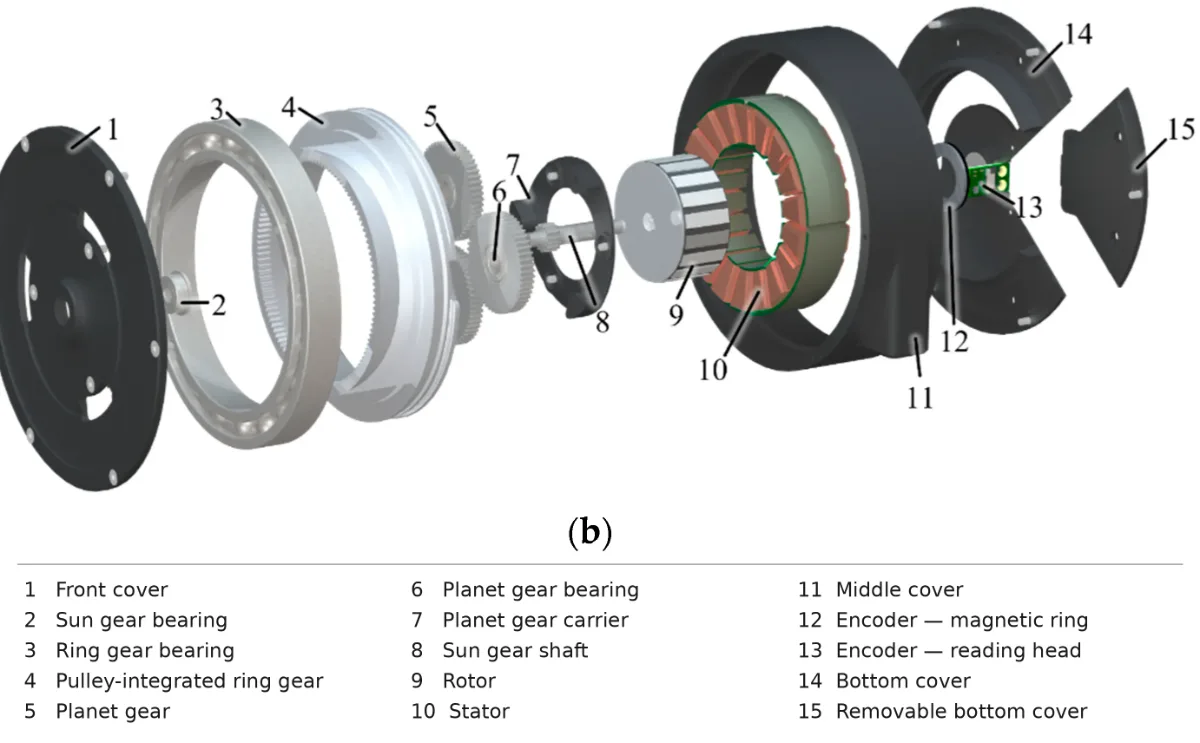
We’ll be starting with a bunch of jargon, so if you start feeling lost, just remember: a motor is fast, but weak. But otherwise: read slowly, refer to the glossary and believe in yourself.
The motor kicks off the process, creating the initial fast, weak torque that must be converted into something useful.
A motor converts electricity into rotation, depending on two facts of physics: 1) moving electric charge creates a magnetic field and 2) a wire carrying current inside a magnetic field feels a sideways push. Combine them, line up some magnets, and you can push a rotor around continuously.
The measure of that push is torque, measured in newton-meters. Some torque is required just to stay in place (imagine standing and letting your muscles all relax—you’d slump to the ground), but actually moving requires speed too. Simply put: Torque × Speed = Power.
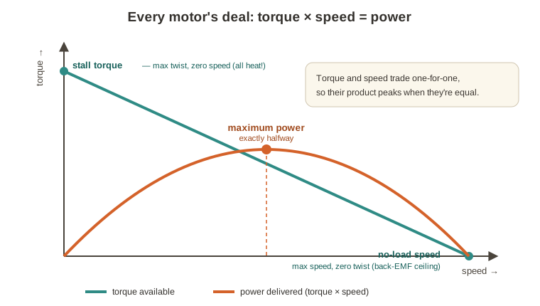
When current moves through a coil, a voltage is induced that opposes it (it’s sort of like pushing a shopping cart with a fan on it: the faster you go, the more wind resistance in your face). This is back electromotive force, or back-EMF, and it’s what fundamentally limits a motor’s top speed. When back-EMF equals the supply voltage, no more current can flow. That same property, run in reverse, is called regenerative braking, which lets a decelerating motor act as a generator. The practical upshot is that every motor trades speed for torque along a spectrum from stall torque (max torque, zero speed) to no-load speed (max speed, zero torque), with maximum power at the midpoint—for a fixed sum, a product is largest when the numbers are equal (5×5 > 6×4).
The overwhelming majority of actuator motors are brushless DC motors (BLDC), which have four key parts:
Stator – the stationary part holding the windings (copper coils) on a core of electrical steel.
Rotor – the spinning part holding the magnets, which are NdFeB (neodymium), a rare earth material majority-mined and almost exclusively separated and refined in China. (That’s important, and we’ll get back to it.)
Controller/inverter – instead of brushes mechanically switching which coil is live (as in an old brushed motor), power electronics energize the stator coils in sequence—this switching is called commutation—creating a rotating magnetic field that the rotor’s magnets chase. No sliding contacts to spark or wear out, which is why BLDC is the workhorse.
Encoder – the controller can only commutate correctly if it knows exactly where the rotor is. (Much more on encoders later.)
Between rotor magnets and stator teeth is the air gap: smaller means more torque, but shrink it too far and the rotor scrapes the stator. The windings are wired in three phases, driven in a repeating sequence. And BLDCs come in two layouts: inrunners (magnets spin inside the stator; higher speed) and outrunners (a magnet bell spins around the outside; higher torque). Outrunners are preferred for direct-drive, load-bearing robot joints, while inrunners remain standard for high-speed or precision applications.
Driving those three phases smoothly—sinusoidally, rather than in blocky steps—is done via field-oriented control (FOC), using pulse-width modulation (PWM): the rapid flipping of power on and off to each phase. The electronics section digs into all of this; for now, know that good commutation needs three measurements—rotor angle (encoders), phase currents (small sensors on the inverter) and shaft torque (inferred or measured; see sensing).
A motor’s performance is ultimately limited by its ability to tolerate heat, primarily caused by copper losses in the windings: heat rises with the square of current, so doubling torque means quadrupling heat. This is why peak torque and continuous torque are such different numbers. Heat can leave by conduction (stator iron → housing → frame), convection (into the air, limited unless you add a fan) or liquid cooling (oil or water-glycol channels, common in EVs and cutting-edge humanoids). The worst case is heat reaching the magnets, which will make them… demagnetize, at which point the entire actuator, nay, the entire robot, becomes—and this is important—a totally useless piece of garbage.
Two smaller but real performance inhibitors: cogging torque, a friction-like preference for certain rotor angles, and torque ripple, any unwanted variation in output that costs precision.
A motor spins fast and weak; a joint needs to move slowly and with strength. Bridging that mismatch is the job of the actuator’s architecture, and it is the decision that defines an actuator—every other choice flows from it. An architecture mostly answers two questions: how much gear reduction sits between motor and joint, and where the motor is mounted. When you hear about different “types” of actuators, someone has made a different choice on one of these axes.
✶The mechanics of reduction
The gear ratio (or reduction ratio) sets the joint’s capability. It is how many turns of the input (motor) produce one turn of the output (joint). At 100:1, the output turns once for every 100 motor turns and delivers roughly 100x the torque—power is conserved; you’re trading speed for strength. Theoretically, anyway. This is robotics, not that Japanese reality show where everyone is nice, so there will be some friction. If the gearbox cuts speed 100x but multiplies torque only 90x, it’s 90% efficient—and as with motors, efficiency is a curve that worsens toward peak load, not a single number.
✶The reduction spectrum: direct drive, QDD and high reduction
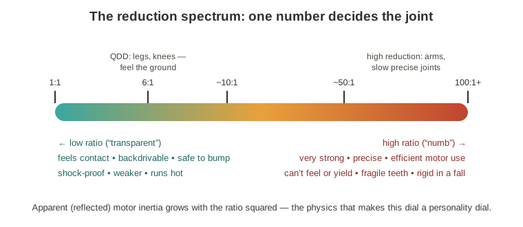
Every joint has to choose to feel the world (low ratio) or overpower it (high ratio).
Quasi-direct drive (QDD) pairs a low gear ratio (5:1, 10:1) with a big motor. High-reduction actuators use harmonic or cycloidal gearboxes at 100:1 and beyond with a small motor. (Tendon drives sit in between.) This single number drives everything because it sets two properties that pull in opposite directions: backdrivability and torque density.
Backdrivability asks: what happens if you push on the joint? If it gives, it’s backdrivable—and a backdrivable robot can feel through its joints. Some backdrivability is effectively a must-have for a robot that walks or works near humans; there is no way to walk well if you can’t sense the difference between mud, grass and concrete. It’s why Boston Dynamics’ Atlas demo a decade ago was a big deal: it walked on different surfaces! It got shoved and didn’t fall down!
The reason high ratios kill this is reflected inertia. A motor has inertia (J_motor); accelerating it (α_motor) takes torque (τ_motor) and we’re trying to solve for the torque at the output joint (τ_output). Through a gearbox of ratio N:
τ_output = N × τ_motor = N × J_motor × α_motor
and since the output only moves 1/N as far, α_motor = α_output × N, so:
τ_output = N² × J_motor × α_output
And so, reflected inertia scales with the square of the gear ratio. A 99:1 harmonic-drive leg meeting the ground effectively absorbs the whole impact with its gear teeth, and breaks; a 6:1 QDD leg shrugs, and can even read the impact straight from motor current without requiring a torque sensor. The cost of QDD is that torque now comes from the motor itself, which must be big and heavy.
✶Gearbox mechanisms
Three gearboxes rule robotics: planetary (the workhorse), harmonic (the precision instrument), cycloidal (the powerhouse).
▸ Planetary gearsets
The QDD gearbox of choice. A sun gear (input) sits at the center, meshing with (typically three) planet gears on a carrier (output), all inside a ring gear (fixed)—ratio = 1 + R/S, from the ring and sun tooth counts. Planetaries are coaxial (input and output on one axis, which simplifies design), split load across several planets (good torque density) and stack—a single stage usually runs 4:1–8:1, but you can pile stages to 100:1 if you want. Backlash is moderate; efficiency is ~95–98% per stage, so each stage you add costs a couple percent. The jack of all trades, and often that’s exactly what you’re looking for.
▸ Harmonic drive (strain wave)
Announced in 1957,13BEEP!13The gearbox has been around since 1957, commercialized by a company whose name now doubles as the category: Harmonic Drive Systems. They’re the Kleenex of actuators. and made of three parts: a wave generator (an elliptical hub in a thin flexible bearing), a flexspline (a thin elastic steel cup with external teeth) and a circular spline (a rigid ring with internal teeth—typically two more of them). The wave generator stretches the flexspline into an oval so it engages the ring at only the two ends of the ellipse; spin it, and the contact points travel around the rim like a wave. Because the flexspline has (usually two) fewer teeth than the circular spline, each revolution walks the cup backward two teeth: a 200-tooth ring gives 99:1 reduction in a single pancake-sized stage.
Their best feature is zero backlash—many teeth engaged at once, preloaded by the elliptical strain, so there’s effectively no gap between gear teeth. Harmonic drives are light, compact and highly repeatable: if you need precision, they’re ideal. The cons: the flexspline fatigues (you get a fixed number of flex cycles and that’s it), torque density is hard to improve, lost motion and hysteresis (roughly: the gearbox’s sense of what position it’s in) limit response, shock loads strain them and they’re expensive. They’re great for arms, research platforms and other slow, precise joints, but imperfect environments punish them.
▸ Cycloidal drive
An off-center hub (the eccentric) on the input shaft pushes a wavy-edged disc that rolls around inside a housing studded with pins; because the disc has one lobe fewer than there are pins, it retreats one lobe per input revolution. Ratios of 11:1–87:1 per stage are common (with some as low as 9:1), and two discs are usually mounted 180° out of phase to cancel vibration.
Versus harmonic: much higher torque density (the load is spread across many pins), far better shock tolerance, better efficiency at peak load, lower hysteresis—and, best of all as a practical matter, the core design is long off-patent (Braren patented it in 1925), so vertical integrators can make their own—though modern refinements remain proprietary. The downsides are real backlash, some torque ripple and more demanding precision in manufacture. Cycloidal reducers are drawing supply-chain investment. Nabtesco has launched compact lines aimed at humanoids and expanded RV capacity, and researchers are prototyping cycloidal QDD joints, though no production humanoid I’m aware of is on the record as using them.
✶How gears fail
Gear failure modes are weirdly analogous to human tooth decay. Pitting (tiny fatigue craters on the tooth flank) progresses to spalling (chunks flaking off). Bending fatigue starts a crack at the tooth root and propagates until the tooth breaks off—this is very bad. Scuffing is metal-to-metal welding when the lubricant film fails, and the lubricant itself degrades with heat, water and contamination, making everything else likelier. Harmonic drives add their special flexspline fatigue (use those flexes wisely). And even without drama, all gearboxes wear: backlash that started near zero can grow severalfold as wear accumulates.
✶Tendon drives
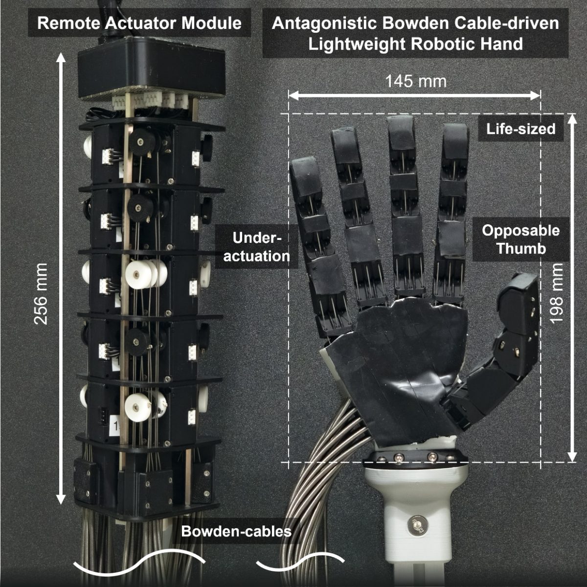
Tendons move the muscle out of the limb, but create additional friction as a result.
Reduction is one design choice; another is where you put the motor. A tendon drive moves it somewhere else entirely—motors mounted centrally in the torso or forearm, connected to joints by cables running through sheaths (Bowden tubes, basically your bike’s brake cables). This is how you, a human, are built: the muscles that flex your fingers are in your forearm, pulling long tendons. The payoff is the same too—mass leaves the limb, so a tendon-driven finger can be as slender as a real one.
Cables only pull, though; push one and it goes slack. The fix is antagonistic pairing—two cables pulling against each other, like your biceps and triceps—which as a bonus makes tendon drives uniquely good at variable stiffness: soft and compliant for human contact one moment, stiff and precise the next. But control is difficult. Every bend in a sheath adds friction (a cable routed through 180° of bends can lose 20–30% of its force), and friction opposes whichever way the cable last moved, creating a “deadband” on reversal that makes precise control notoriously hard. Tendon actuators are also the weakest—heavy payloads are not their thing.
Their natural home is hands, and almost any robot with a hand-shaped gripper is using them. But not exclusively: 1X Technologies’ NEO uses a full-body tendon drive—central brushless motors, tendons to the limbs—on the theory that a compliant, quiet robot beats a strong one at home.
✶Linear (screw-driven) actuators
A screw turns spin into push, and holds position easily, which makes them the ideal fit for humanoid knees.
Every actuator we’ve covered so far spins the joint. There’s another way—the one in the legs of most serious humanoids: don’t spin the joint, push it.
A linear actuator works the way a muscle does. Your calf doesn’t rotate your ankle directly; it pulls a tendon, which pulls your heel, which acts as a little lever and swings the joint. In hardware: a motor spins a screw, a nut riding the screw slides in a straight line (that’s the “muscle”) and the push works a short lever at the joint. Mount it alongside the shin like muscle laid on bone and you get a slim limb with the heavy part tucked out of the way. Tesla’s Optimus, Figure and the electric Atlas (probably—at the least they have a patent) all bend knees and ankles this way;14BEEP!14By the count that’s circulated publicly, Optimus runs about fourteen of these reversed roller screws, roughly eight in the legs—something like half the robot’s actuator count. if rotary owns the shoulders and hips, linear owns the legs.
At the heart of it is a simple machine: the screw. Picture a scissor car jack, which turns many easy rotations into a small, immensely strong push. It trades speed for force exactly like a gearbox, just in a straight line. There are three versions to know.
The lead screw is a plain nut on a plain rod. It’s cheap, holds position when you let go, but metal grinds on metal—fine for slow jobs, not for a knee.
The ball screw solves that friction the way a moving crew does: it puts the box on wheels. Tiny steel balls sit in the threads and roll as the nut turns, so barely anything is lost to friction. It’s smooth and efficient, but its weakness is that each ball meets the thread at a single pinpoint—like standing in stiletto heels, all your weight driven through tiny spots, so the repeated pounding of walking eventually dents them.
The planetary roller screw is the one that owns the humanoid leg. Instead of balls, it uses grooved rollers that spiral around the screw and mesh with its threads along their entire length. Because they touch along lines rather than dots (flat shoes instead of stilettos), the load spreads out, and the PRS screw manages impacts that would wreck a ball screw. It handles several times more force for its size and lasts a long time. The catch is that it’s hard to make. Optimus uses a space-saving variant called an inverted planetary roller screw with the parts turned inside-out: the rollers orbit inside a spinning outer sleeve while the screw itself shoots in and out.
A screw has “gearing” too—how far the nut travels per turn—and that decides whether the joint can feel. A fine thread is heavy gearing-down, producing enormous force and slow motion. A fine thread self-locks—shove the load and it won’t budge (that’s why the car jack holds the car when you stop cranking). A steep thread is the opposite: less force, but if you push the load, the screw spins back. (There it is again, backdrivability!) Roller screws took over humanoid legs because when tuned right, they generate real force and enough backdrivability to feel the ground, in a compact package, sensing load straight from motor current. For a knee that must absorb a landing one instant and heave the robot upright the next, that’s the whole wishlist.
Two caveats. First, geometry: a linear actuator shoves on a lever, so its strength varies with joint angle (think of how a wrench feels powerful at a right angle, but awkward elsewhere). You can exploit this by arranging the linkage so the knee is strongest near full extension, braced to stand—but the software must compensate, and a screw only extends so far, so the joint sweeps a limited arc. This is fine for knees and ankles but useless for a shoulder that has to windmill. Second, they’re just hard to make or get. The threads on the screw, the nut and every roller are ground to microns on machines only a handful of companies know how to run, and they’re all at capacity. The roller screw is the leg’s harmonic drive—a highly precise part with a supply chokepoint—though Chinese manufacturers hurrying in can only drag prices down.
✶Other architectures
Everything above—electric motor, gearbox, motor at or near the joint—covers the overwhelming majority of humanoid and quadruped actuators, which is why it gets the overwhelming majority of this document. But wait, there’s more!
Series-elastic actuators (SEA) put a deliberate spring between gearbox and joint:15BEEP!15Agility’s Cassie ran leaf-spring SEAs in its legs—suspension doing double duty as a force sensor—and that lineage carries into Digit, part of why it moves like it’s walking on eggshells, gently, on purpose. shock tolerance, energy storage and clean force control: measure the spring’s deflection—how far the load has bent it from its resting shape—and, because springs deflect in proportion to force, you’ve measured the force. The trade is bandwidth—the spring that protects the joint also slows it.
Hydraulics ruled the athletic era—the original Atlas did parkour on hydraulics—but they’re leaky, inefficient, maintenance-heavy and loud (think of RoboCop making all his RoboCop sounds). In April 2024, Boston Dynamics retired hydraulic Atlas and rebuilt it all-electric. Pneumatics, which use compressed air, appear in soft grippers, but rarely in load-bearing joints.
✶How we got here
From the 1980s through the 2010s, harmonic drives dominated robot joints; they now mostly live in arms, wrists and other slow, precise joints, where fatigue-limited flexsplines, expense and shock-failure don’t matter much. For legs, QDD won. The weight and power cost of a big motor is worth the bandwidth, backdrivability and impact tolerance. The highest-load joints went linear, to roller screws. The open question is the middle of the market: strong rotary joints that take a beating. That’s where cycloidal drives are being positioned—positioned, but not necessarily productionized. No production humanoid is publicly documented running cycloidal joints (Optimus’s rotary joints are understood to use harmonic drives), but the supply chain is preparing.16BEEP!16Nabtesco has launched compact cycloidal lines aimed squarely at humanoids and expanded RV capacity after acquiring Spinea, and researchers are prototyping cycloidal quasi-direct-drive joints. Shock tolerance, torque density and a foundational geometry whose patent expired decades ago.
Challenges, of course, remain. Heat: continuous torque is capped by motor heating, the gearbox is often the thermal bottleneck and reflected inertia dumps braking energy back into the motor as heat—solving this would mean far higher continuous torque from the same size motor. Lifetime: humanoid duty cycles are peaky in ways industrial fatigue models weren’t built for, so those fatigue models likely underestimate failure rates. And cost: the gearbox is the most expensive part of the actuator, which is the most expensive part of the robot.
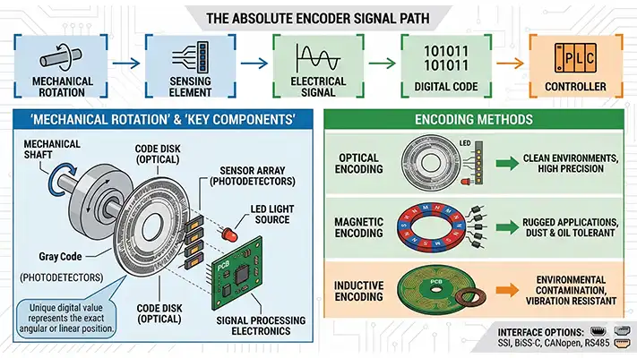
An encoder tracks position—and if you know position and can measure time, you also know speed and acceleration. Inside an actuator, the flow is: motor → encoder #1 (motor-side) → gearbox → encoder #2 (joint-side) → joint. It’s generally two encoders, because the gearbox between them creates errors (backlash, flex), but cheaper actuators make do with the motor-side one alone.
Magnetic encoders are the default. A small permanent magnet sits on the shaft’s end; a sensor chip sits a millimeter or two below and reads the field’s direction as an angle. It’s basically a compass. Chips read the field via one of several effects, from the Hall effect (cheap, robust, modest resolution) to tunneling magnetoresistance (TMR), which uses quantum tunneling, has the best signal-to-noise, and will continue to gain share in new designs. (In between sit anisotropic magnetoresistance (AMR) and giant magnetoresistance (GMR), which are admittedly being skipped past, though the GMR folks did get, like, a science award for their work.)
Magnetic encoders are resistant to dirt and moisture, cost little and live on the motor-driver board. For real-world robots, that’s just… better than the alternatives; worse best-case accuracy doesn’t matter when there are no best cases. Their weakness is stray magnetism—and the encoder lives close to the motor, which has a big ol’ magnet.
Optical encoders shine an LED through a patterned disc onto photodetectors; the flicker uniquely identifies the angle—Morse code for robots. They’re the most precise, but contaminants garble the message, so they stay in sterile industrial machines. Inductive encoders skip the magnet entirely: printed coils broadcast and listen while a wavy-edged metal tag spins between them, like a fan turning between speakers and microphones. They’re slightly thicker, but tough, cheap, fully digital, and immune to the motor’s magnetism. They’re well-suited to tight, motor-adjacent joints.
An encoder can, uh, encode its information one of two ways. An incremental encoder reports changes in position; an absolute encoder reports position, period. It’s “I walked past four doors, so I’m at the fifth” versus “I can read the number on the door even if I’m just waking up from a fugue state.” Absolute is objectively better—no “re-homing” on startup—and robotics is shifting toward it, though both have a place. On any spec sheet, check three numbers: resolution (smallest reportable change), accuracy (closeness to truth) and repeatability (consistency at the same position). You get what you pay for, so know which one you’re paying for.
The encoder’s reading travels over a serial protocol; there are three main ones: SSI (simple, no error-checking, increasingly legacy), BiSS-C (open, error-checked, bidirectional—displacing SSI) and EnDat 2.2 (Heidenhain’s option).
In a harmonic-drive actuator, you need both motor-side and joint-side encoders. Motor-side gives high-resolution rotor angle but not the true joint angle; joint-side gives the joint angle but terrible motor resolution. With real-world lost motion in the gearbox, dual encoders are pretty essential. In QDD, torque comes from current rather than deflection, so one encoder usually suffices for torque measurement (though a second is often added for position), creating simpler, lighter, faster control loops.
✶Force and torque
Feeling force costs money and calculating it costs accuracy.
There are three ways to sense force, presented here in rough order of cost. Cheapest: don’t measure it, infer it from motor current, which in a permanent-magnet motor is nearly proportional to torque. A QDD actuator, with low ratio and modest friction, gets joint torque essentially free; this is one of QDD’s advantages.
Second: read the gearbox’s own deflection. In a high-reduction joint, encoders on both sides treat the windup between them as a torque measurement, which is the second reason for dual encoders: position and force at once.
Third: a dedicated torque sensor, a flexure that bends measurably under load. This is most accurate, but most expensive, and adds compliance and calibration burden. The extreme version is the series-elastic actuator, whose spring is so soft you can read force with an ordinary encoder. Most humanoid joints skip it and lean on current or deflection.
✦Trendwatch: sensing
The high-level trends: TMR chips winning at the low end17BEEP!17TMR output is roughly 20x an AMR sensor’s and 6x a GMR sensor’s, per TDK., inductive displacing magnetic and resolvers at the mid/high end, dual encoders dominating humanoid joints, BiSS-C as the open protocol.
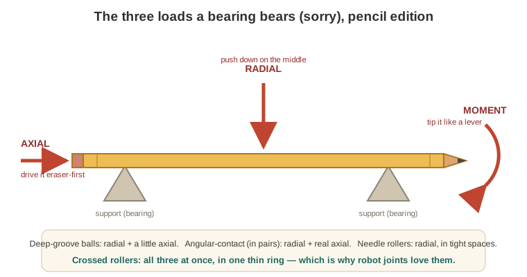
With a crossed roller, one thin ring can carry all three loads at once, which makes it suited for many robot joints.
Lots of things in this guide spin, which means surfaces gliding past each other, which means two problems: friction and wander. A bearing’s entire job is to hold one rotating thing in place relative to another with as little friction as possible. They sit in three places—inside the motor, inside the gearbox and at the output joint—and they bear (I’m sorry, I don’t see a way around that) three kinds of load, which I will use pencil-based analogies to explain.
Radial load is force pushing on the shaft sideways. If you held a pencil horizontally and pushed down on the middle, that’s a radial load on whatever is supporting the sides. Try to drive it eraser-first through its support and that’s axial load; grab it far from the support and tip it like a lever and that’s a moment load.
Each bearing carries two ratings: static load capacity (the point where a stationary bearing’s balls start denting the races) and dynamic load (an estimate of the load at which 90% of bearings survive a million revolutions). For robots, the static number—which is tested more by sudden impacts than the dynamic one—likely matters more.
New ball bearings ship with a smidge of internal clearance—for thermal expansion and lubricant flow—but clearance is play, and play is position error. The fix is preload: squeezing the clearance out (with a nut, spring or slightly oversized shaft) so every ball is always in firm contact. Preload trades stiffness against friction and life: a heavily preloaded bearing is rigid and precise but wears faster. At the output joint that’s a good trade; inside the motor and gearbox, usually it’s not. Stiffness is generally the bearing’s headline stat because it’s a hard upper limit on how precisely the joint can be controlled.
A plain bearing (bushing) is just a sleeve of slippery material the shaft rides in—quiet, cheap, huge load capacity, but more friction at low speed. In robots they take the low-stakes jobs (idler pulleys, linkages, light grippers, often as self-lubricating polymer bushings). Deep-groove ball bearings are the cheap prototypical kind—great radially, moderate axially—and live inside motors. Angular-contact bearings tilt the ball contact to carry axial load in one direction (mount them in pairs for both) and commonly ride the harmonic drive’s wave generator. Cylindrical and needle rollers trade axial capacity for high radial capacity in tight spaces—planet gears usually spin on needle bearings.
Last but certainly not least is the beloved crossed roller bearing, which is the standard in industrial-arm and humanoid output joints. Its cylindrical rollers alternate at 90° to each other, so adjacent rollers brace in perpendicular directions—one thin ring carries radial load, axial load both ways and moments in two axes. Five degrees of freedom constrained, the sixth (rotation) set free; without it you’d need two spaced angular-contact bearings to do the same job. Japan’s THK leads supply, with IKO gaining traction alongside Schaeffler, Kaydon (an SKF brand) and a growing list of Chinese makers.
✶How bearings fail
To paraphrase Tolstoy: all happy bearings are alike; each unhappy bearing is unhappy in one of, well, a handful of ways. The natural death—fatigue spalling, where a subsurface crack finally lifts a flake off the race—essentially never arrives in humanoids; something else gets there first. Brinelling is when the race is permanently dented by static overload—this is what falls and crashes cause. Fretting corrosion is tiny oscillations between a race and mounting, shedding reddish debris; this is driven by sustained vibration. Lubricant death comes from age or contamination, and since most bearings are “lubricated for life” (meaning: cannot be re-lubricated), there’s nothing to do but watch the joint die.
Perhaps the most important failure mode in robotic bearings is electrical fluting. The motor’s drive switches voltage fast and not perfectly symmetrically, leaving a small high-frequency voltage on the rotor. When the voltage punches through the lubricant film, it vaporizes a microscopic crater. Millions of sparks later, the craters organize into regular grooves, like a record’s—that’s fluting, and a fluted bearing is a dying bearing. Hybrid ceramic bearings (silicon-nitride balls don’t conduct—no path, no fluting), insulated races, or shaft-grounding rings that give the current a safer road home are potential fixes, with hybrid ceramics at the motor as the popular but expensive choice at two to three times the price of steel.
Where failures happen tracks where bearings live: output bearings brinell and fret; motor bearings flute and age; gearbox bearings eat gear-wear debris. Mercifully, bearings die gradually rather than suddenly and are relatively unlikely to be the first component to give out.
✦Trendwatch: bearings
The industry is moving toward integrated actuators—motor, gearbox, bearing, encoder, brake in one sealed unit—where the bearing gets co-designed with the gearbox and encoder for tighter tolerances. Harmonic joints show where this leads: the wave generator relies on continuous elastic flexing,18BEEP!18A design factor widely cited as governing flexspline fatigue life. and Harmonic Drive’s standard Gear Units ship with the output crossed roller bearing already integrated into the gear unit housing.
Sensorized bearings—sensors built into the bearing itself, reading elastic deflection for predictive maintenance and even live stiffness compensation—remain just out of reach. Many have tried; it’s unclear if anyone has managed to ship at a reasonable price. Full-ceramic bearings tempt weight-obsessed humanoid designers (silicon-nitride rolling elements are only about 40% as dense as bearing steel, but several times the price). And monitoring: a MEMS accelerometer that costs only a couple dollars plus a simple model can hear fluting or fatigue beginning—predictive maintenance cheap enough to put on every joint. Several robotics companies are building it in.
Fair warning: electronics is the most jargon-y and technical part of the guide. If you only take one thing from it, take this—the electronics turn a request (“40 newton-meters, please”) into thousands of precisely timed electrical pushes per second. If you find that you are in active pain as you read this, return to this paragraph, reread that sentence and move on.
The electronics are the conduit through which commands are issued and executed—they exist, at root, to do commutation (the process by which the electronics figure out where the rotor is). They come in three parts: the MCU (microcontroller) is the brain, a small CPU running real-time control software; the gate driver IC is the translator, converting the MCU’s tiny logic signals into properly timed high-current signals; and the power stage is the muscle, an array of MOSFETs—transistors used as pure switches, fully on or fully off—that pour battery current into the windings.
✶The power stage
The power stage does one thing: it connects each of the motor’s three phase wires to either the battery’s positive terminal or its negative one, tens of thousands of times per second, in whatever pattern the MCU requests.
Picture three vertical stacks, each with two MOSFETs: a “high-side” switch to the battery’s positive rail, a “low-side” switch to ground, with the motor phase wire tapping off the middle. One stack is a half-bridge; three in parallel make the three-phase inverter (or “B6 bridge”) that converts the battery’s DC into the three-phase AC the motor wants.
A word of warning: if both MOSFETs in a stack switch on at once—called shoot-through—you get a dead short and instant failure. The guard is dead time, a tiny enforced gap between one switch turning off and the other turning on; but dead time causes losses, so designs compensate in software and cut the losses the gap incurs in hardware (gallium-nitride (GaN) MOSFETs are state of the art here). The power stage also carries a bank of bus capacitors to smooth the gulps of current, plus the shunt resistors that measure phase currents for FOC.
✶The gate driver IC
The gate driver is the motor neuron of the actuator. It takes the MCU’s whisper of a signal and turns it into a shove strong enough to snap the big switches open and shut—millions of times a minute, with built-in reflexes (dead time, fault trips) that keep the muscle from tearing itself.
The gate driver takes the MCU’s outputs and level-shifts them to what the MOSFETs need (usually via a bootstrap circuit), while inserting hardware dead time and monitoring temperature and current for trouble. The speed at which it can flip a MOSFET is the slew rate; faster is better, except that faster also means more electromagnetic noise. Everything is a tradeoff; you know that by now.
✶The MCU and its software
I am in a very small segment of a barely touching Venn diagram of “likes robots” and “doesn’t like Marvel movies,” and so I do not have an MCU joke. Sorry.
The MCU is a small embedded computer—the off-the-shelf favorite is the ARM Cortex-M series, though as far as I can tell, major humanoid players are moving en masse to custom ASICs (chips designed for exactly this job; huge upfront cost, better speed and efficiency, and—at volume—better price). Several thousand times a second, it asks four questions: Where is the motor right now? (the encoder). How much current is flowing in each coil? (the shunts). What does the robot want this joint to be doing? (the command from the central computer). And what voltage pattern should I push into the coils next, to move things closer to what’s wanted? The last one it computes, and hands to the gate driver as a stream of on/off pulses.
The algorithm doing the computing is FOC (field-oriented control), and it deserves a plain-language attempt, because it is secretly one idea.
Start with the problem. To make smooth torque, the controller must push current through three sets of coils in endless, perfectly timed waves—each rising and falling in sync with the spinning rotor, forever. Control software is bad at chasing moving targets and great at holding steady ones: the humble thermostat-style controller (a “PI controller”—correct in proportion to the error, push harder the longer it persists; five lines of code, you know, like Raspberry Pi) can hold “70 degrees” all day but cannot chase a wave to save its life. So motor control looks hard: three moving targets, changing thousands of times a second.
FOC’s whole trick is to make the motion disappear. Imagine you’re on a merry-go-round and a friend stands beside you: to everyone else, they’re a blur, but to you, they’re motionless. FOC does that mathematically—it hops aboard the spinning rotor,19BEEP!19The Clarke and Park transforms, if you’re keeping score at home. and from that seat, the three frantic waves become two numbers that just… sit there.
Better: the two numbers mean something physical. One is push—current shoving the rotor around its circle, the way you’d push a revolving door along its face. That’s torque; the robot asks for some amount of it. The other is squeeze—current shoving straight at the hub, which turns nothing and only makes heat. You want squeeze at exactly zero.
And now the hard problem is a thermostat problem: hold “push” at whatever the robot wants, hold “squeeze” at zero—one five-line controller each. Their outputs get rotated back out into the real, spinning world and handed to the switches as timing patterns. Measure, hop on, adjust two dials, hop off, switch. That is FOC: it converts “chase three waves” into “hold two numbers,” which is what lets a cheap microcontroller produce smooth, exact torque.
In practice, one full pulse-width modulation (PWM) cycle runs: currents sampled → results land in MCU memory → encoder read → all the FOC math above → new duty cycles written and buffered to take effect next period → miscellaneous low-urgency tasks in the slack time → repeat. The whole loop takes about 50 microseconds, so 20,000 times a second.
✦Trendwatch: electronics
Four things to watch out for: GaN and silicon carbide (SiC) are wide-bandgap semiconductors. TI reports GaN switching up to roughly 7x IGBT frequencies, and GaN prices are falling, with some parts crossing below $1. Integrated power modules that fuse MOSFETs, driver and sensing into one package (TI, Allegro, ST). Model-predictive control replacing PI loops—predict each candidate switching state, pick the best—newly feasible on M7/RISC-V cores. Custom silicon—Tesla, Boston Dynamics and Figure increasingly pack more of the stack onto custom die (Apptronik, notably, runs on off-the-shelf TI parts).
It’s better if a robot doesn’t fall on you when its power goes out. Thus, brakes.
Recall the tricky spot a backdrivable QDD actuator is in: backdrivability lets a robot feel the world through its joints, but it cuts both ways—a backdrivable joint can’t hold a position once you stop driving it. To keep a QDD arm frozen mid-pose, the motor must keep pushing current, putting off a staggering amount of heat just to stand still.
So, brakes! A common type used in servo applications is the spring-applied, electromagnetically-released holding brake (“power-off brake”). The crucial property is that it engages when power is removed. That’s fail-safe in the most literal sense—cut the power, by e-stop or by fault, and every braked joint locks instead of collapsing. A second common electromagnetic design uses permanent magnets instead of springs.
As a holding brake, it lets a backdrivable joint hold a pose with the motor cool and de-energized, directly attacking the QDD heat problem. Brakes add mass, length and a trickle of standby power, so designers weigh placement carefully—though typically every movable joint needs some way to brake and hold.
There is, though, an ongoing discussion of how exactly failure handling should work for home robots. Some argue that locking leads to bigger, more dramatic falls, so it’ll be interesting to see whether brakes are more defined by technological advances or by bureaucrats in Switzerland who, in extraordinarily Swiss fashion, claim to be part of “a global network of the world’s leading standardizers.” I suppose I have a preference. (Swiss bureaucrats, ofc).
Heat is, generally speaking, the cause of actuator failure, and the housing is the primary escape route. Thermal-engineering studies of enclosed motor housings show natural convection typically carries roughly 70% of the heat leaving the surface, with radiation accounting for the rest.
The housing is really six things at once: structural support (a 20 kg payload’s moment runs through the elbow housing), clamping fixture, heat sink, environmental seal (water, dust, your dog’s hair), EMI shield (a Faraday cage around those switching transistors), and safety interlock between fingers and hot fast things. These jobs are in conflict: an ideal heat sink wants thin walls and fins; an ideal backbone wants thick walls; an ideal seal wants no openings. Housing design is the management of that fight.
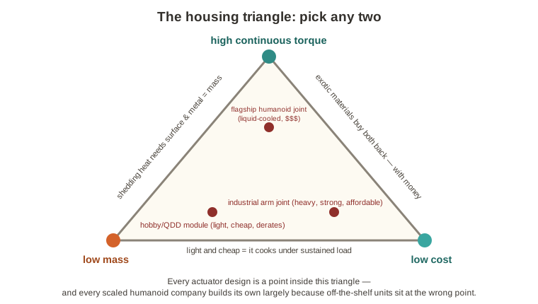
A motor can briefly make three to four times its continuous torque, and heat scales with the square of current—quadruple the torque, 16x the heat. Peak torque is what physics permits for a fraction of a second; continuous torque is what thermal management permits forever, and the ratio between them is set mostly by the housing-and-cooling design.
The ability to shed heat is performance per kilogram.
✶Materials and manufacturing
It’s mostly aluminum: light, stiff, rust-resistant, easy to machine, and—crucially—an excellent heat conductor at a low price. There’s speculation about using lighter magnesium alloys, though no confirmed per-robot weight-savings figure exists—and magnesium burns and conducts heat much worse, so it can’t take over wholesale. Steel is for stationary industry; plastics (PEEK, PPS, carbon-fiber composites) serve low-load housings.
Manufacturing follows a standard arc: prototype with CNC machining (no tooling cost, and you can change the geometry by editing a file, but slow, and every subtracted gram is wasted material and machine time), then shift volume production to high-pressure die casting—molten metal forced into a steel mold, five-to-six-figure tooling ($10K–$100K+), months of lead time, then fast near-net parts with cooling channels cast right in. This is the “high fixed cost, low marginal cost” option, familiar from Tesla’s gigacastings. The housing itself is rarely what fails on its own; adjacent gearbox-failure literature suggests that when enclosure-level failures do occur, they tend to trace to a defect, design error or impact event rather than routine wear (direct robot-actuator housing failure data is scarce).
✶Hot! Hot! Hot!
The most important thing to remember: heat rises with the square of current, so torque gets quadratically expensive. In an illustrative example, let’s take 100 W of electrical power flowing through an actuator at cruise. Maybe it looks like: 80 W of useful mechanical work; 12 W of copper losses (heat in the windings); 5 W of iron losses (heat in the laminations); 5 W mechanical (friction, windage); 3 W in the electronics. That’s 80% useful—at cruise. At peak transient torque, the useful fraction falls: to ~60% if the joint is moving fast, ~30% when slowly muscling a load and 0% at dead stall, where all input becomes heat. So remember: holding a heavy pose indefinitely puts off a lot of heat.
Heat is bad, guys. Hot windings heat the magnets, lowering their flux, so the same torque needs more current, making more heat—a vicious cycle. Hot windings thin the gearbox lubricant; hot bearings lose preload; hot encoders drift; hot electronics derate or quit. Every part of the actuator hates heat.
Some anti-heat solutions roughly in order of exoticism: thermal interface materials (TIMs, lol—silicones and waxes that fill air gaps between surfaces); larger aluminum surface so that the housing acts as a heat sink; fans (spot-cooling knees, hips, even faces in some humanoids already); liquid cooling loops (big, noisy and breakable—good for managed settings only); hollow-shaft cooling (run coolant through the rotor itself, attacking the magnet problem directly); heat pipes and vapor chambers (sealed tubes whose internal fluid ferries heat by evaporating—proven elsewhere and already shipping here—the Unitree G1 cools its joints with copper vapor chambers); phase-change buffers near the stator (the material melts during an overload, clamping temperature—buys time for a jump, doesn’t cool continuously); and potting—filling the winding air gaps with thermally conductive epoxy, which many humanoid actuators now do (3D-printed coils shrink those gaps further).
✦Trendwatch: housing and heat
Pick any two: high continuous torque, low mass, low cost. Continuous torque is set by thermal management; thermal management needs surface area and conductivity, which create mass; lightening the housing costs stiffness or surface; buying performance back with exotic materials costs money. Every actuator design picks a point on this triangle—and as far as I can tell, every scaled humanoid company builds its own actuators in large part because off-the-shelf units land on the wrong point of it.
Where heat concentrates depends on the gearbox, in ascending order of how much the design is a heat problem.
Planetary: losses spread across stages; standard potting suffices; not especially performant, but not too hot either!
Cycloidal: heat pools at the eccentric bearing, whose chunky steel absorbs heat the way it absorbs impacts—which is why punished hip and leg joints like cycloidals; “thermal mass” does mean mass.
Harmonic: heat collects in the magnets (faster motor, more iron loss; the fix is roughly “buy a really good magnet”) and in the gearbox—flexspline, wave-generator bearing, grease—and there isn’t much to be done about a hot flexspline, so that’s the hard limit.
QDD: more than anything else, a heat-management problem—the big motor’s windings take nearly all the loss, so all the spaghetti gets flung at the wall: potting, maximum slot fill, short copper-to-housing paths, the housing as a giant heat sink, liquid cooling on performance joints. And since QDD can’t hold a static load without current, it pays the full stall-equals-all-heat penalty.
Note that the two most performant architectures sit at the bottom of this list. Performance is gated by heat.
A few thoughts on what’s next in the thrilling world of housing and heat management. Direct conductor (slot) cooling means running coolant through hollow copper conductors inside the stator slots, collecting heat at the source instead of pushing it through the windings-to-coolant path that is usually the thermal bottleneck; Formula E and aerospace already do it.
Magnetically geared actuators would mean throwing out every gearbox in this document and instead transmitting torque through modulated magnetic fields. That’d be no contact, no gear-friction heat, no lubricant, plus free overload protection (the gear simply slips) and free backdrivability. Torque density isn’t competitive yet, but this has the highest possible impact, because it deletes an entire heat source and the lubrication problem all at once.
The hand is where everything you’ve just learned about motors, tendons, encoders and heat is miniaturized into a space the size of, well, a hand, and then asked to be gentle and more precise. Solving hands is the hardest challenge in actuation.
Elon Musk: “The Optimus hand and forearm is an incredibly difficult engineering challenge. I’d say it’s more difficult than the rest of the robot… The forearm and hand are more difficult than the entire rest of the robot.”
The hand is the general actuator problem, only more so and smaller. Everything hard about a humanoid—packing strength, sensing and precision into cramped, lightweight quarters—recurs inside an object the size of, well, your hand.
The human hand has about 27 degrees of freedom: four per finger, five for the thumb (ooh, aah, impressive!), plus the wrist. And several of the muscles that power your fingers aren’t in your hand at all—they’re in your forearm, pulling long tendons, with only small “intrinsic” muscles on site. Your fingers are light because they’re remote-controlled. Have you ever seen a weightlifter’s fingers? They’re still pretty much average fingers.
Robot hands have two options. Path one is underactuation: fewer motors than joints, with springs and linkages passively spreading the grip so fingers wrap whatever they touch. Motors are a hand’s biggest, costliest components, so fewer means cheaper, lighter, tougher—warehouse robots happily run two-fingered grippers and suction cups, and Agility’s Digit started with no fingers at all, only now moving to swappable hands—a kind of clever “I dunno, you guys figure it out” approach. Path two is to replicate the human hand.
The Shadow Dexterous Hand, built in Britain since the 2000s, has been path two’s apex: 20 motor-driven degrees of freedom, tendon transmission, over a hundred sensors, 4.3 kg—the hand OpenAI used to solve a Rubik’s Cube one-handed. It also costs over 100,000 Swiss francs (~$110–125k) and is, per research surveys, hard to maintain.
The current generation splits across three architectures. Wuji Tech’s hand uses 20 tiny direct-drive motors embedded in the fingers themselves—no tendons, no palm motors—backdrivable, sensing contact through motor current: QDD shrunk to finger scale. Reviewers call it “extremely robust,” though the base model has no tactile skin, and about $15,500 buys a seventh of a Shadow for the same 20 DOF. Tesla’s Gen 3 hand goes the other way: 22 DOF driven by ~25 actuators per side, essentially all moved out of the palm and into the forearm, pulling tendons exactly like your extrinsic muscles—fifty actuators (!) in the hands versus twenty-eight for the entire rest of the body. 1X’s new NEO hands push the same tendon logic furthest: 25 DOF on quasi-direct-drive tendons at 5:1–15:1, every joint backdrivable and force-controlled, with hundreds claimed off an in-house line and capacity for 10,000 this year (though as I’ve said elsewhere: capacity is not production). Figure went cheaper-and-smarter with softer, more adaptive fingertips, first-generation tactile sensors and a camera in each palm. And Sanctuary AI still uses hydraulics—in a finger-sized space, hydraulic power density is at a premium—with 21-DOF hands driven by coin-sized valves claiming two billion test cycles without a leak20BEEP!20Sanctuary’s fingertip pads read pressure through arrays of micro-barometers—the same category of chip that tells your phone which floor of a building you’re on, repurposed to feel how hard a hand is squeezing. (hydraulics can leak—often).
The long tail: China’s Inspire Robotics supplies the five-fingered hands on many Chinese humanoids; Unitree sells a three-fingered Dex3-1 and a 20-DOF Dex5; Korea’s Allegro hand fills university labs at a fifth of a Shadow’s price; and PSYONIC, fascinatingly, arrived from prosthetics—its Ability Hand (490 g, six motors, touch-sensing fingertips, closing in 200 ms) now ships on research robots at NASA, Meta and Apptronik.
As I’ve, uh, touched on before, robot touch is hard. Perhaps the best robotic skin is MIT’s GelSight: a camera inside the fingertip filming the back of a soft gel pad as it deforms, converting touch into 3D imagery; its Meta collaboration produced Digit 360, detecting forces down to a millinewton—instrumentation your fingertips would envy. Whether all that feeling proves useful or just “that’s neat” remains open.
So when someone asks why the robot revolution is behind schedule, you can now answer with authority in two words: the hands. They’re where every demon in this document—packaging, heat, tendon wear, sensing, cost—throws its farewell party, all at once, in a space the size of a deck of cards.
✦Trendwatch: hands
Touch is gaining prominence, and within it the key sub-sense is shear: the sideways drag of something starting to slide—think of the sensation you feel as a glass slips out of your hand. 1X claims progress here. Designs are converging on twenty to twenty-five knuckles’ worth of motion, whether via motors in the forearm (Tesla, 1X) or direct-drive motors embedded in the fingers (Wuji), even as the transmissions diverge—tendons, in-finger motors, micro-hydraulics. And the price curve has found fingers: six figures a few years ago, a fifth of that, now $15,500 for twenty DOF—with designs increasingly judged by how well they survive years of a learning algorithm’s practice. Your hand has seventeen thousand touch receptors and a lifetime of practice. The bar is high.
Wow, what a journey that was. You made it; take a water break, you’ve earned it (if you skipped straight to this section, take one anyway—hydration is still important).
We’ll go over the process of building an actuator, from raw stock to an actual usable unit for the low, low price of $191. For the sake of this example, we’ll focus on QDD actuators, which have a big motor and a low gear ratio (6:1 is fairly typical). The analysis covers a family of three sizes sharing one architecture, scaled for the major joint classes of a ~1.7 m humanoid:
We’re assuming 100k actuators, which would be roughly enough to support 3k robots/year—not a huge number, but a useful place to start.
A QDD actuator is, basically, five things: a stack of electrical steel, a coil of copper, some rare-earth magnets, a block of aluminum and a set of hardened-steel gears. Bearings and electronics are usually bought from an external vendor.21BEEP!21Linear actuators would tell a similar story: screw threads wear the way gear teeth do—slowly roughening, losing precision before anything dramatic happens—and they’re priced the same way too, dominated by hours of precision grinding rather than materials.
A note on prices before we start: everything here assumes best-value global sourcing—China-direct OEM pricing wherever a two-tier market exists—with Western prices flagged as the contrast. That’s how every scaled builder actually buys.
Let’s review the made-in-house materials, one by one:
Non-grain-oriented electrical steel (NGO / silicon steel). The stator and rotor laminations are stamped from thin-gauge non-grain-oriented silicon steel. Frameless motors run at high electrical frequency (20+ magnet poles, spinning fast), and eddy-current losses (bad!) scale steeply with lamination thickness—thus, thin-gauge. Standard-grade NGO steel has traded around $755–815/tonne FOB Shanghai (~$0.80/kg); the thin low-loss grades these motors need carry a real premium—budget ~$2–3/kg China-direct.22BEEP!22US-produced premium NGO ran $5.3–5.6/kg in early 2026—one of the widest East–West price spreads anywhere in the BOM. Stamping yield is poor—the slots and center bore become scrap—so only about half of purchased mass ends up in the stack, though the scrap sells back.
Sintered NdFeB magnets. Bulk motor-grade NdFeB ran roughly $60–130/kg in 2026 depending on grade and heavy-rare-earth content, having jumped 30–50% off 2025 lows—the floor of that range is raw-blank, standard-grade pricing (SH-class blanks alone run ~$45/kg after the rally). Budget ~$75–95/kg finished at China-direct prices—the table uses $85—and the band is still being squeezed upward: NdPr alloy jumped 21% in June alone. Magnets are bought pre-cut and coated but magnetized in-house after assembly, since handling live magnets is dangerous and error-prone. Rare-earth supply is the single biggest cost and geopolitical risk in the whole bill of materials (BOM).
Copper magnet wire. The stator winding uses enameled round copper wire. With copper around $13,000–13,700/tonne in 202623BEEP!23As rich man and poor man alike know—it touched an all-time high above $14,500 in January before pulling back. Copper’s price is the most erratic of all of these, so these numbers may be out of date by the time you read this., enameled wire lands near ~$16.5–19/kg in bulk. Rectangular “hairpin” wire packs more copper into the slot but needs different equipment; round wire with needle winding is the cost-effective default at this scale.
Aluminum. Housings, the output flange and the planet carrier are machined from aluminum—mostly 6061-T6 for cost, stepping up to 7075-T651 where loads demand. Blended, budget ~$8.8/kg of billet—deliberately above raw mill pricing, since billet form and alloy mix carry a premium over ingot.
Gear steel. Sun, planets and ring are cut from case-hardening alloy steel (9310 or 8620 for the sun and planets, sometimes 4140/4340 through-hardened for the ring). Bar stock is cheap—$2.0–2.5/kg for annealed bar at mill-direct volume (hardened distributor stock runs about double)—but the value added in cutting, hardening and grinding dwarfs the raw material. Hold that thought.
And the bought-finished parts: the output bearing (a crossed-roller or paired thin-section unit that takes the joint’s moment load in a thin axial space; priced by the bearing specialists at ~$14/$24/$40 across S/M/L—one of the two largest bought items, with small motor-shaft and planet needle bearings adding a few dollars more; that’s 100k-unit OEM contract pricing from Chinese manufacturers—brand-name catalog prices for comparable bearings run 3–10x higher); the output absolute encoder (a magnetic sensor IC reading a magnetized target, plus a small flex/PCB: ~$5–7); the motor controller electronics (a 3-phase power stage, gate driver, MCU, current sensing, network transceiver and connectors on one compact board in the rear cavity: ~$18/$28/$40, scaling with the power stage); and ~$4–11 of consumables—fasteners, seals, grease, thermal interface material, potting, labels. It’s just not worth making commoditized stuff.
Notice the pattern: the costs that scale with size are raw materials (magnets, gears); the ones that don’t are the purchased items (encoders). And notice what best-value sourcing did and didn’t do: the raw-material lines moved, but the subtotal barely did—bought components dominate, and they set the floor. As we’ll explore, vertical integration moves the needle most on the housing, gears, stator and rotor.
Now that we have our raw materials, we need to convert them into something useful. Thus, a factory. Five fabrication value-streams—lamination stamping, stator winding, rotor build, gear manufacturing, aluminum machining—converge into motor and gearbox sub-assemblies, then final assembly and end-of-line test. Nine steps, raw stock to shipped unit. For each, the interactive cost console at the end of “What our actuator actually costs” prices the step per actuator, Small/Medium/Large—and keep an eye on the split between labor and machine time, because that split is where the entire economics of this factory lives.

1. Stamping the steel core. What this step makes: the steel skeleton of the motor—the stationary stator and part of the spinning rotor.
A motor’s core is a stack of many thin steel sheets pressed together like a deck of cards (a solid core would waste energy as heat; thin insulated layers run far more efficiently). Each layer is a lamination. For cheap production in huge numbers, steel arrives as a long coil and feeds a stamping press—an industrialized cookie cutter—that punches out each layer complete with its slots and center hole. The die that does the punching costs $150–400k per size, but it lasts millions of parts, so it adds almost nothing per unit. The punched layers are glued into a stack and lightly heat-treated to relax the punching stress. About half the steel becomes scrap, sold back for recycling.
2. Winding the stator. What this step makes: the electrical “muscle”—the copper coils whose current creates the magnetic force.
The stator’s slots get filled with many turns of fine insulated copper wire, threaded back and forth by a winding machine—like winding thread onto a spool, but far more precise. The wire ends are terminated so the controller can power them, and the whole assembly is coated in a varnish that’s baked hard. That varnish does two jobs: it glues the coils in place so they don’t buzz loose under vibration, and it helps carry heat out of the copper. Copper is floppy and awkward and resists full automation, which makes this the most hands-on of the motor steps.
3. Building the rotor. What this step makes: the part that actually spins.
The rotor is a steel drum carrying a ring of permanent magnets. Curved magnet pieces are glued on in a fixture that spaces them evenly, then wrapped with a thin retaining band (carbon-fiber or stainless) so they can’t fly off at speed. Two finishing touches matter: the rotor is balanced, like a car tire, so it spins without vibration—and only at the very end of the process are the magnets actually magnetized. They’re deliberately kept “switched off” until then, because handling live magnets is dangerous: they snap together violently and grab any stray metal, which is fun in a factory-blooper way and bad in every other way.
4. The control board. What this step makes: the actuator’s brain.
The board that switches power into the motor and reads the encoder gets built on an automated electronics line: solder paste down, dozens of tiny components placed with robotic precision, solder melted to lock everything in, cameras inspecting the result, then a protective coating. Companies build these in-house mainly to control supply and to keep hardware and software in sync—not because it’s hard; the line finishes a board in seconds.
5. Making the gears. What this step makes: the parts that multiply the motor’s turning force—and the biggest bill in the building.
The gear set is a planetary: a central sun gear driven by the motor, planets circling it, an internally-toothed ring around them. Gears are the hardest parts to make well, for two reasons: they must be cut to extreme precision, and they must be very hard so they don’t wear. The process runs in four stages—blanks are turned on a lathe; teeth are cut; the gears are hardened in a furnace (same idea as hardening a knife blade); and then, because hardening slightly warps the teeth, each gear is ground back to its final shape with a precision abrasive wheel. That final grinding is what makes the gearbox quiet and tight—and it’s the most expensive part of the whole step.
6. Machining the aluminum casing. What this step makes: the shell and structure that hold everything together and bolt it to the robot.
CNC machines whittle solid aluminum blocks down to exact shape—the seats where bearings and motor sit must be accurate to a fraction of a millimeter, or the actuator won’t run smoothly. To keep costs down, robots tend the machines, which run nearly around the clock, including lights-out overnight. After cutting: deburr, wash, anodize (the electrochemical surface-hardening treatment from phones and water bottles). A lot of the original block leaves as shavings, recovered and resold.
7. Sub-assembly (motor and gearbox). What this step makes: two finished modules, ready to be combined.
Up to now the factory has made loose parts; here they start coming together. The gearbox build fits sun, planets and ring into their carrier, checks that they mesh with very little wobble and greases them. The motor build fits the copper-wound stator and magnet-carrying rotor into the housing along with the main bearing. The trickiest detail is the air gap between rotor and stator: it’s a fraction of a millimeter, and it must be even all the way around or the motor loses power. Special fixtures set it precisely, and the position sensor is fitted and aligned here too.
8. Final assembly. What this step makes: An actuator!!!!
Motor module meets gearbox module; the control board is wired in and tucked into the back, and the whole unit is closed up with seals—rubber rings, like the gasket on a jar lid—to keep dust and water out. Every bolt is tightened by tools that measure and record the torque: too loose and parts work free, too tight and they crack.
9. Testing and calibration. What this step does: tests and fine-tunes every single unit before it ships.
Each finished actuator is mounted on a test stand—a machine that spins it and pushes against it to measure how it really performs. Four things happen: calibration (the actuator is “taught” its own exact position-sensing, saved into its memory); a performance check (strength, smoothness, efficiency, gear play, warm-up behavior—does it meet spec?); burn-in (run under load for a while, because most failures show up in the first hours of life); and a safety and electrical check, with the final approved software loaded. Every result is recorded against the unit’s serial number, forever. Passing units are packaged for delivery.
After nine easy steps, here’s what we owe. Add a 6% yield/scrap allowance and 18% manufacturing overhead24BEEP!24Roughly automotive standard—there’s reason to believe a single-product, brand-new line could do better, though. to the 100k-unit points on curves that tighten with volume, as we’ll see below, and the full cost structure of our honest-to-goodness QDD actuator emerges:
Play with the volume dial and the story gets interesting:
The cost falls hard from 100k to 1M to 10M; then the curve flattens as fixed costs amortize away and you hit a floor made of raw material, energy and irreducible machine time—gear grinding and aluminum cutting take a certain number of seconds no matter how many machines run in parallel. Material and bought parts are roughly 60% of the 10M-unit cost, drifting toward two-thirds by 100M.25BEEP!25The yield allowance tightens from 8% → 2.5% across the columns and overhead from 20% → 9%, as process control and amortization improve with volume. And the 100M/yr column is theoretical—it implies ~3 million robots a year, more than global car production, at which point the material line would probably rise, since it means stretching the world’s rare-earth supply.
Still: this is part of the appeal of in-house manufacturing. The catch is upfront. Order-of-magnitude equipment and tooling: stamping dies and presses $1–3M; winding and varnish $1–2M; gear cutting, grinding and heat treating $5–12M (yeesh—precision gear grinders run $0.5–1.5M+ apiece depending on tier); CNC cells and automation $4–10M; electronics line $1.5–3M; balancers and magnetizers $0.5–1.5M; test stands and burn-in $3–8M. Add fixtures, installation and spares to those machinery lines, and total plant capex is plausibly $20–45M before working capital—the same capex-per-unit ballpark as EV e-axle plants—and the per-unit machine burden, far more than the day-rate of labor, is the number to manage. If you’re going to invest heavily in machines, you need to get your money’s worth.
In general, the way to lower costs is the three R’s: reduce, reuse, recycle. Stop wasting metal, stop correcting problems downstream and start preventing them upstream and stop paying people to do what a machine can repeat. Subtractive machining, downstream finishing and touch labor get expensive at volume. Most of the solutions below are lifted from automotive and EV manufacturing—they’re generally proven, but waiting for robot volumes to justify them. Figures anchor on the Medium actuator; dollar deltas are directional.
Magnets (~$7.7 and rising). Put the expensive element only where it works: grain-boundary diffusion concentrates dysprosium/terbium at the magnet’s grain boundaries instead of alloying it throughout—same heat resistance, 50–70% less heavy rare earth, roughly 15–30% off magnet cost and it’s automotive-standard: you don’t build it, you specify it.26BEEP!26Tesla doesn’t make magnets. It buys 3.5 kg of NdFeB per robot, largely from China—and has been hunting for alternatives since April 2025. Beyond that: Halbach-style rotors squeeze more torque from less magnet (niche—assembly is hard); near-net-pressed and axially-segmented magnets waste less and lose less; and for supply, dual-source, contract long, qualify recycled feedstock—or, for joints that can afford the bulk, design the rare earth out entirely with wound-field or ferrite-assisted motors, as BMW already ships in volume—Renault and Nissan run wound-rotor machines in the ZOE and Ariya (E-Mobility Engineering), and Astemo targets ferrite-assisted production around 2030. Cars have room to trade torque density for cost; a compact humanoid joint usually doesn’t. Treat it as a hedge for selected joints, not a plan.
Gears (~$13.6, one of the two biggest in-house lines). The route today: turn a blank → cut teeth → carburize and harden → grind the warp back out. Grinding eats over half the machine time in the gear cell, so the master key is: almost every gear lever is an attack on grinding. The big one is to stop creating the distortion you’re paying to remove—low-pressure (vacuum) carburizing with high-pressure gas quench cools parts uniformly, so teeth exit heat-treat in nearly final shape and grinding drops to a quick pass (or, on lightly-loaded planets, disappears). Established automotive practice, worth roughly $3–5 per gear line, ~$1.5–3M per cell, paying from ~100k units/year. Do it first; the others depend on it.
The receipts, briefly: power skiving has moved into mainstream automotive production because it conquered internal gears, which previously required slow shaping; gear honing is an increasingly common automotive hard-finishing step alongside grinding, because honed flanks run quieter; and powder metal has long been limited in loaded power-transmission gearing by porosity-related tooth-root fatigue—densification techniques are closing that gap, but slowly—which is exactly why it’s a planets-only, high-volume play.
Stack the first three and you recover $5–10 of the $13.6—in this factory, the road to a cheap actuator runs through a grinding wheel.
Housings (~$13.7). Today every housing is carved from a block three times its final weight. The lever is near-net forming: squeeze/semi-solid casting or die casting with machining only on the precision surfaces (bearing seats, stator bore, threads) reduces cutting time by half to two-thirds—$13.7 toward $6–8, with dies at $200k–1M, paying from ~250k–1M units/year. Proven at car scale (gigacasting consolidated ~70 parts into one); waiting on robot volumes at actuator scale. Meanwhile: forge the simple round parts, run remaining machining high-feed and lights-out (10–25% off) and design parts for forming—consolidate housings, cast in the features, budget tolerance only where function demands.
Stator & winding (~$3.8 of touch labor). Copper resists automation; the fix is to change the part, not the worker. Segmented stator cores let each tooth be machine-wound densely, raising slot fill from ~65% to 75–80% and deleting the touch labor; concentrated windings shorten the end-turns (copper that carries current but makes no torque)—already standard in Mini-Cheetah-class motors; hairpin winding waits at 1M+/yr, as in EVs; single-shot potting replaces slow dip-and-bake.
Electronics (~$28 of components + $4.9 assembly). Integrate: discrete MOSFETs + driver become one power module, then at scale one custom ASIC folds driver, sensing and MCU into a single device (a multi-million-dollar, 10M+/yr commitment—Tesla already integrates drive electronics into the Optimus actuator). And question one-board-per-joint: a hand or wrist cluster can run from one multi-channel controller, deleting whole boards—the Optimus hand does exactly this—at the price of wiring and fault-isolation tradeoffs.
Bearings (~$24, the largest bought mechanical item). Spec the cheapest bearing the loads actually allow (paired angular-contacts where a crossed-roller is overkill: $24 → $14–18); at volume, integrate the raceway into parts you already machine—wire-race bearings, grooves cut into your own housing plus hardened wire and rolling elements, a trick cobots already use;27BEEP!27German firm Franke invented the wire-race bearing in 1934. It spent most of a century as a niche industrial curiosity before lightweight cobots noticed that deleting the bearing housing is a great way to delete weight. and dual-source everything else.
Assembly & test (~$27 across three steps). Automate the cells (robotic presses, auto air-gap setting, torque-and-log stations); once the process proves itself, stop burning in every unit and sample instead—100% functional test, statistical burn-in, as electronics manufacturing has done for decades; parallelize the stands and sequence tests to fail fast.
Cross-cutting levers. Platform commonality (one encoder, one controller family, shared bearings and fasteners across all sizes—the cheapest part is the one you don’t make); yield and in-line metrology (the 8% → 2.5% yield-allowance curve in the volume table is this lever); tolerance budgeting (every tolerance tighter than function requires buys a finishing operation somewhere); and vertical-integration timing—bring bearings or magnet finishing in-house only past the volume where it beats contract pricing. Too early strands capital; too late cedes margin. Compute the crossover per part; never assume it.
The great promise of autonomous robotics is that it can make all lives better, not just the wealthy. To accomplish that, actuators need to be better, and they need to be affordable.
If that happens, we can end dangerous and menial labor. We can age in our own homes. We can play with our kids and leave a messy pile of toys to be picked up later.
So here’s what to watch, on the affordability side: whether merchant actuator prices and performance ever match in-house units—that’s build vs. buy. Whether robots shipped ever catch up to robots announced—because capacity is not production. And whether rare-earths are actually getting to the US in a reasonable timeframe—that’s whether our relationship with China is in the right place. And when the company says it’ll cost $20,000 at scale, well… how? Whose magnets, whose reducers, whose factory? How many actuators at what cost each?
And on the capability side: What happens when a robot is shoved—does the arm yield like a limb or shatter like a statue? Is that thing going to fall on my toddler? Does it grab with the dexterity of a human or of an arcade claw machine?
Hopefully the cost curve is steeper than I estimated and scale solves everything. Perhaps the “build vs. buy” equations that I had as generally leaning toward building will see the emergence of suppliers that creep further up the value chain and render robots more generally affordable. An NVIDIA/TSMC dynamic—where the most important part is the design, but the manufacturer does well too—could easily emerge.
But let’s be clear: the robots are coming—the motors are whirring, the gearboxes are improving, the money is committed. What stands between here and a billion useful robots is not necessarily a grand breakthrough, but rather finding the right permutation of thousands of incremental manufacturing decisions of the sort that this document has walked you through, on its linear screws, on series elastic actuators and surely, someday, on something we haven’t even imagined yet.
Every technical term in this document, alphabetized.